Measurement With Scanning Lidar System(thesis)
For my final thesis in 2018 I worked on building a scanning LIDAR system. The idea of this system was that it could be used to detect objects and determine their size form far away or measure how far filled up a container was.
General principle of LIDAR
You can skip this part if you already know what LIDAR is. LIDAR stands for(LIght Detection And Ranging or Laser Imaging Detection And Ranging), it is a method to measure the distance to a target by illuminating the target with pulsed (laser) light and measuring the reflected pulses with a sensor. The distance is calculated using the time that passed between sending the pulsed light and receiving the reflection of the pulsed light. -Wikipedia
Must haves(or constrains) for this project
For this project there were some things that were demanded to be used or operate in a specific way.
- The system had to be build using a SICK LMS200/500 2D LIDAR sensor
- The software was to be written in C#
- Visualisation To be done using a 2.5D (grayscale) image
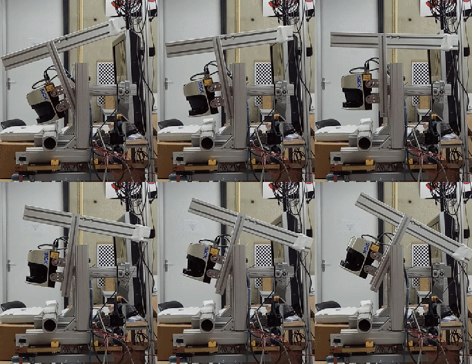
- The sensor had to be oscillating and not continuously rotating
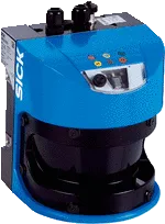
The LIDAR sensor: SICK LMS500
For this project I used a SICK LMS511 2D LIDAR sensor,depending on the environment conditions the sensor can have a scanning range of up to 80 meter. Under bad conditions when te remission(The amount of light that is reflected by an object) is only 10% the max range is 26 meter. The scan angle is 190 degree and the scan frequency can be set from 25Hz to 100Hz, the higher te scan frequency the bigger the distance between two measuring points. This means with how the scanning LIDAR system is setup you wil get a higher scan rate but a lower scan resolution in the horizontal axis.
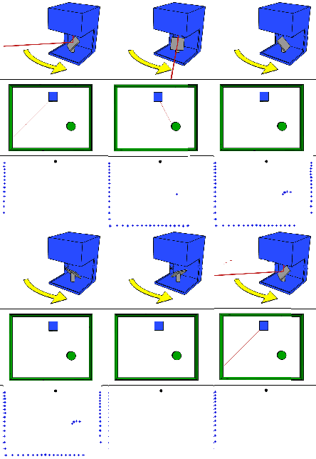
The animation below shows the basic principle of how the 2D LIDAR sensor that is being used in this project works.
Motor and encoder
An Animatics SM2315D motor with a 1:16 gearbox was used to drive the rotation mechanism needed for this system. The nice thing about this motor is that everything needed to use this motor like the speedcontroller, encoder and communication is contained within a single neat package.
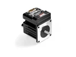
Although the motor has a encoder inside there was still a need for a sepparate encoder that kept track of the amount the LIDAR sensor had rotated. For this a Baumer BNIV 40Z1D26W02048L 6N encoder was used. The range of this encoder can be set from 100 to 25000 pulses per rotation.
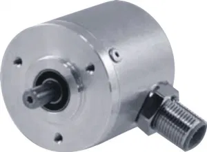
The frame
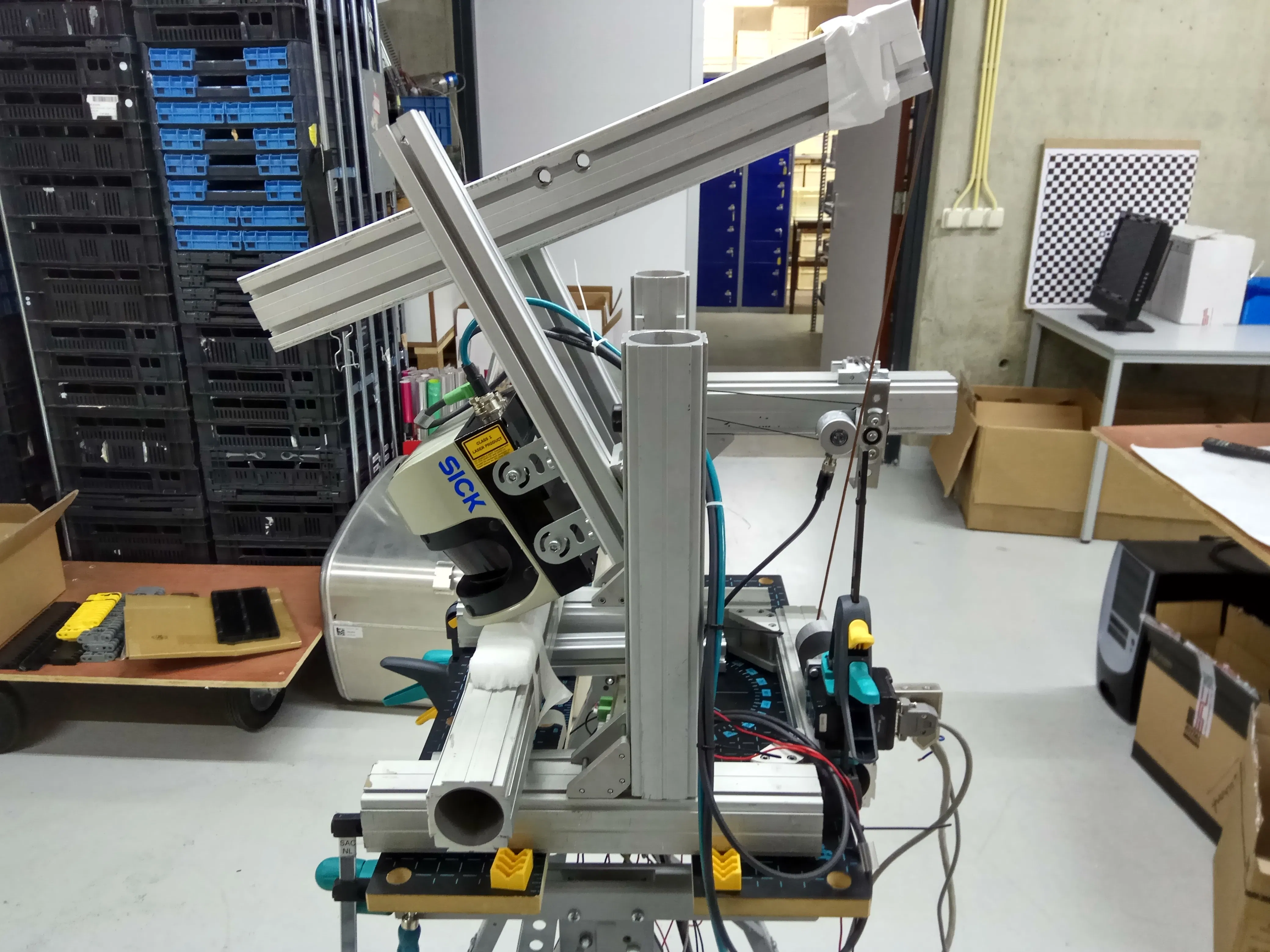
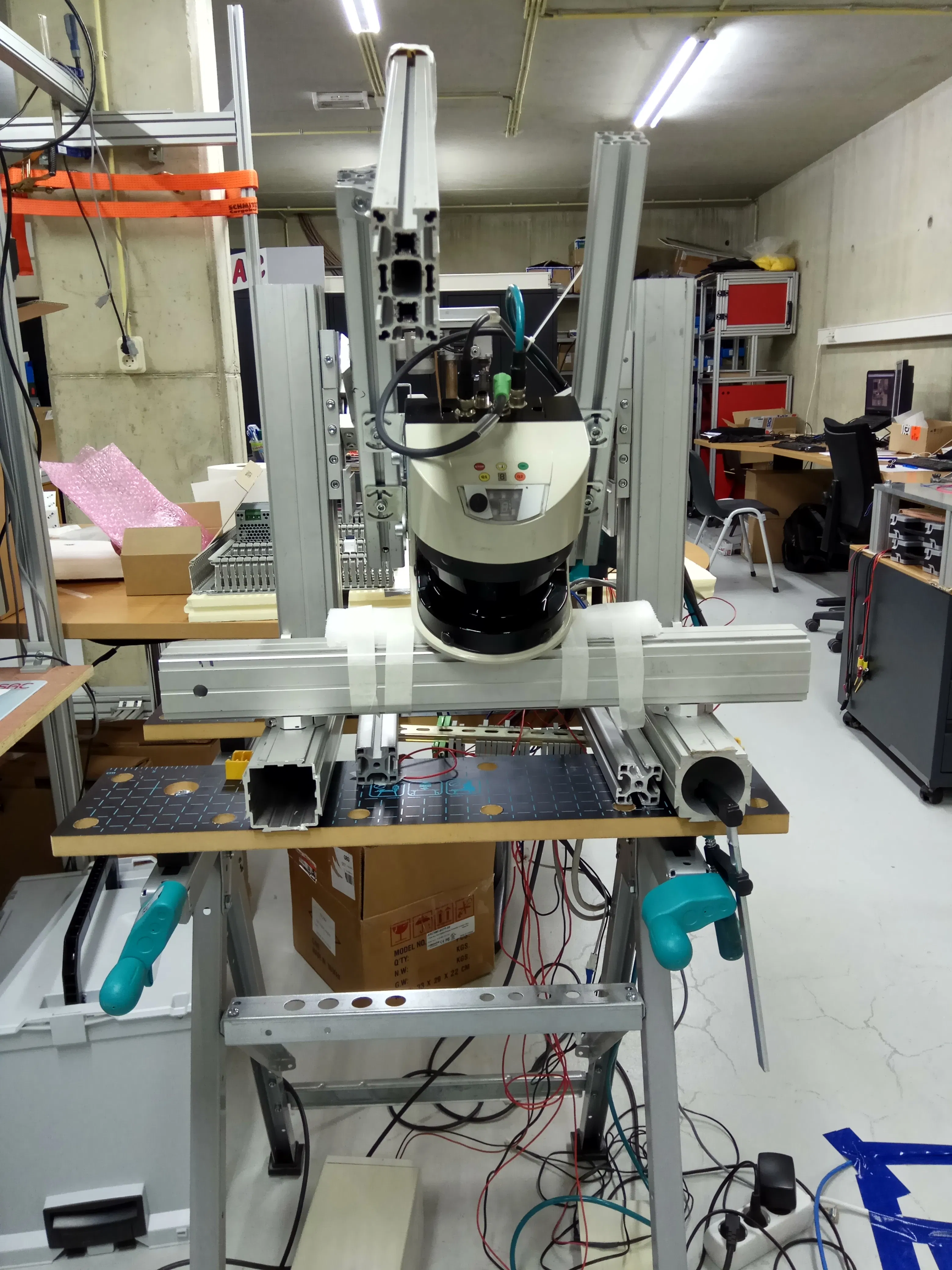
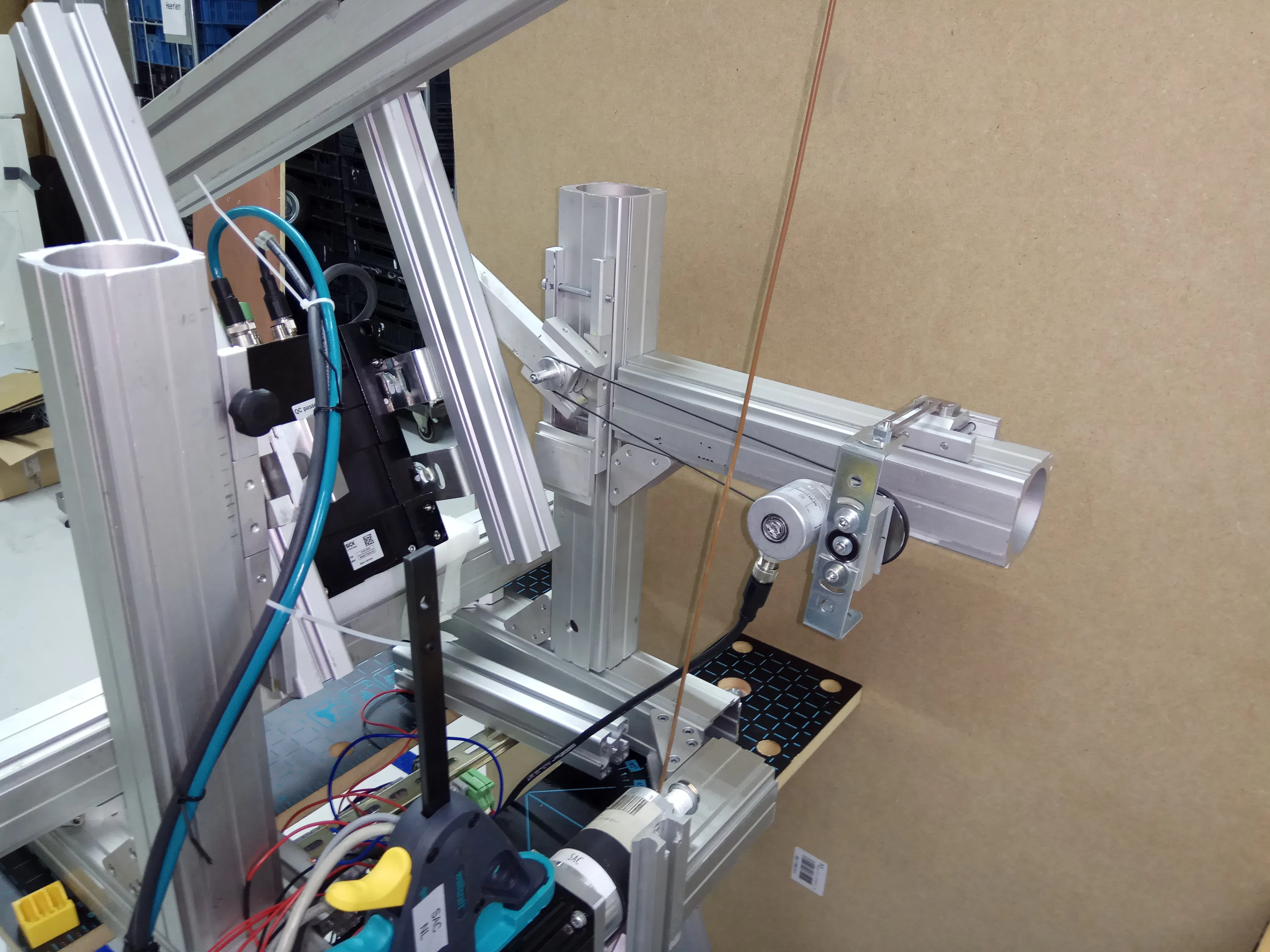
The frame that the sensor is attached and rotates the sensor is build using aluminum extrusions system made by Montech. The reasons for using these extrusions are: its easy to work with for a non mechanical engineer, the extrusions were already available, the company did not have e mechanical workshop and the designs for the mechanical system were not going to be ready to get the parts made before I would graduate. Using the extrusions system I was able de build something that worked good enough to test the software together with the electrical hardware.
Software
The sofware is written in C# as it was one of the demands for this project. I would have preferred using C/C++ or Python at the time because there wase a wide range of opensource libraries available that could have been used for a project like this.(e.g. PointCloudLib)
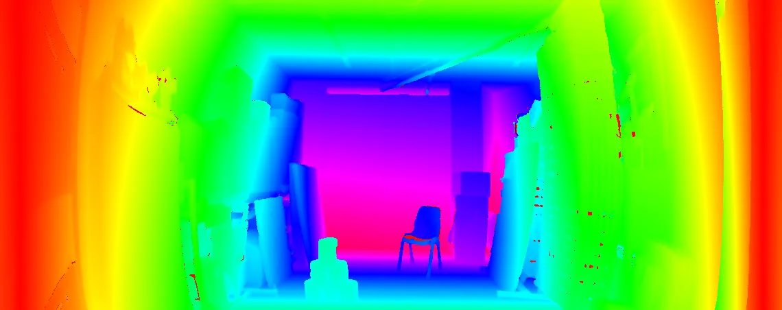
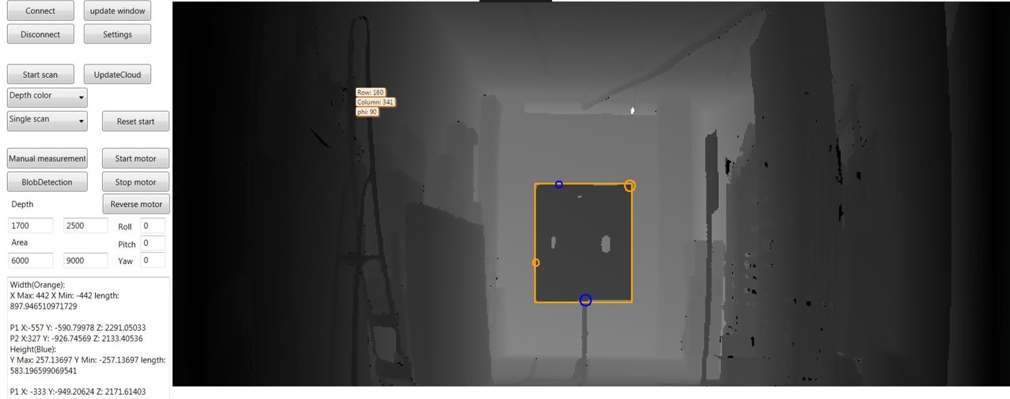
Emgu.CV(C# OpenCV wrapper) was used to draw the 2.5D image and Halcon 13 was used for the blobdetection and pixel selection for measuring tools. Each pixel in the 2.5D image corresponded with a pixel in the 3D pointcloud that was created by the LIDAR sensor. Because the 2.5D image pixels corresponds with a pixel in the 3D pointcloud it was possible to use simple blob detection algoritm to detect an object at a specific distance and size. once an object was detected in the 2.5D image the actual dimensions of an object could be measured by measuring the distance between two points in the points cloud.
The way that the object detection was done is quite error prone as you wil see a bit further down, Because the blob detection in the 2.5D image to get the width and height of an object is not 100% accurate. This causes that sometimes the wrong pixel is selected in the pointcloud data, giving inaccurate reading of the actual size of an object.
End result
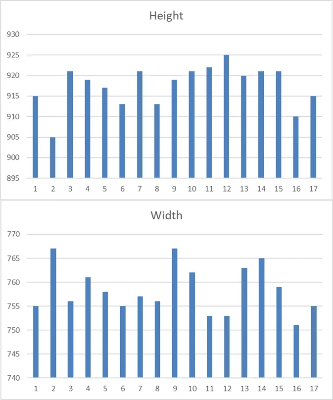
At the end of the 20 weeks that I could work on my thesis project I ended up with a (prototype) 3D LIDAR system that is easely able to scan a large object(~890mm X ~610mm board) from a distance of 2,5 meters with a average deviation in height of 27mm and width 148mm
Considering how the mechanical part to rotate the LMS500 sensor is build and the distance at which the measurements are done, the deviation is not that bad but could be hugely improved using better pointcloud object detection algorithms and a much more stable and consistent platform to mount the LIDAR sensor to.
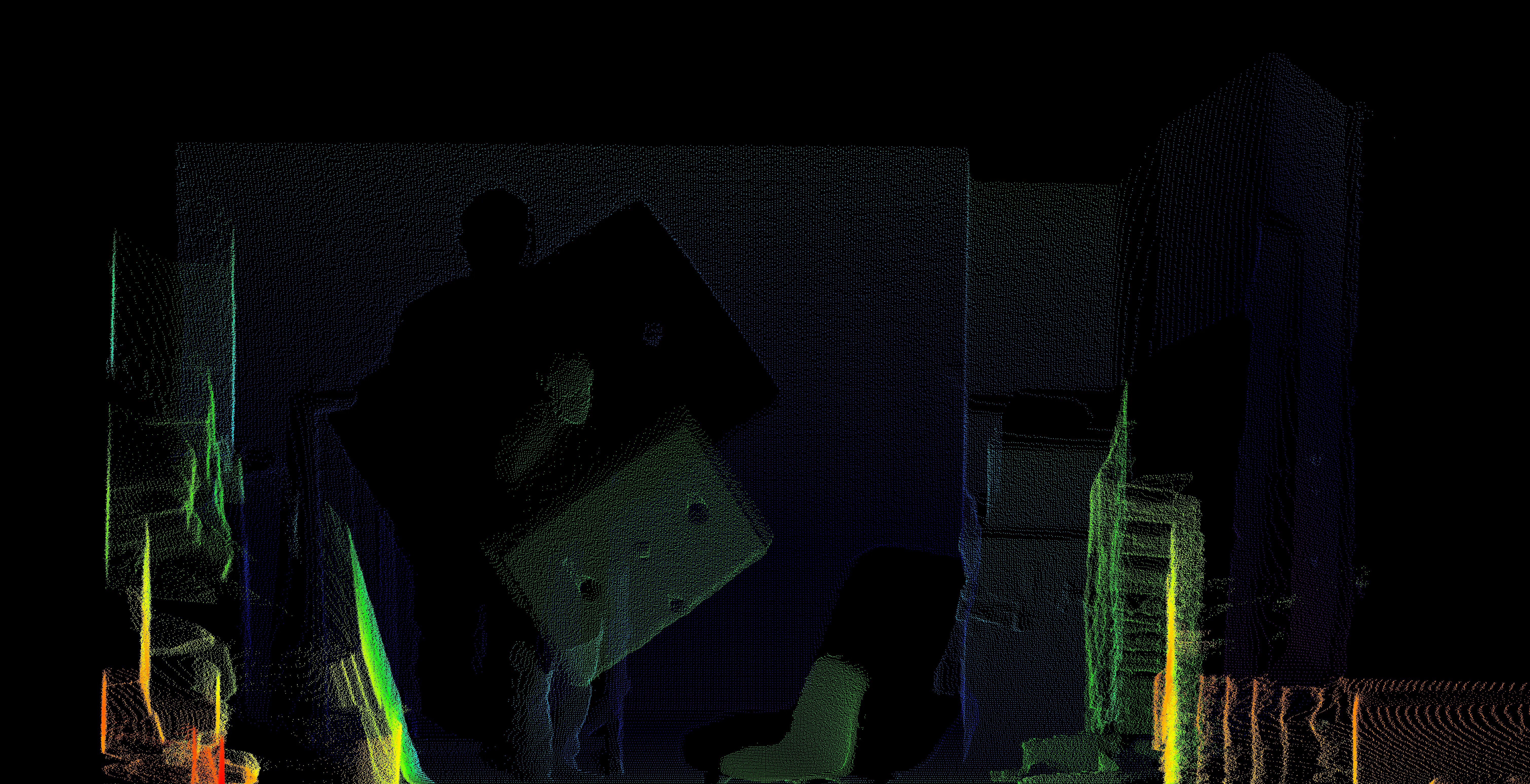
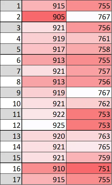
In the graph and excel sheet below you can see how sometimes the measurement is completely wrong for the width, this could be cause by unwanted movement in the platform that the sensor is attached to or mistakes during the blob detection.
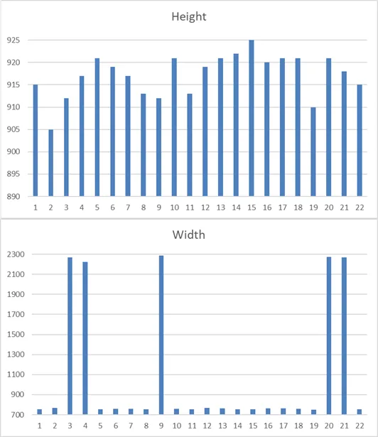
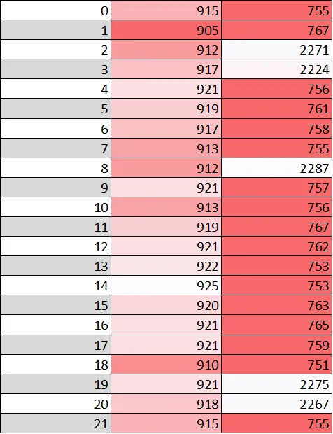
After we get rid of the failed measurements(to make things look a bit better) we can calculate the standard, average, minimum and maximum deviation.
Standard deviation(68,27%):
- Height: 5,09 mm (0.200 Inch)
- Width: 4,96 mm (0.195 inch)
Minimum deviation:
- Height: 15 mm (0.590 inch)
- Width: 141 mm (5.551 inch)
Maximum deviation:
- Height: 35 mm (1.378 inch)
- Width: 157 mm (6.181 inch)
Average deviation:
- Height: 27 mm (1.062 inch)
- Width: 148 mm (5.287 inch)
