3d Printable Pelton Turbine
The main reason that I started this project was to practice working with 3D CAD software and designing 3D printable parts. For this project I have used Fusion 360 for the designing and an Anet-A8 3D printer with ColorFab Ngen filament. The design wil be made opensource after I have made some small changes to fix a few problems with the current design.
What is a Peltonturbine?
The Pelton wheel is an impulse-type water turbine. The Pelton wheel extracts energy from the impulse of moving water, as opposed to water’s dead weight like the traditional overshot water wheel. Many variations of impulse turbines existed prior to Pelton’s design, but they were less efficient than Pelton’s design. Water leaving those wheels typically still had high speed, carrying away much of the dynamic energy brought to the wheels. Pelton’s paddle geometry was designed so that when the rim ran at half the speed of the water jet, the water left the wheel with very little speed; thus his design extracted almost all of the water’s impulse energy—which allowed for a very efficient turbine. -Wikipedia

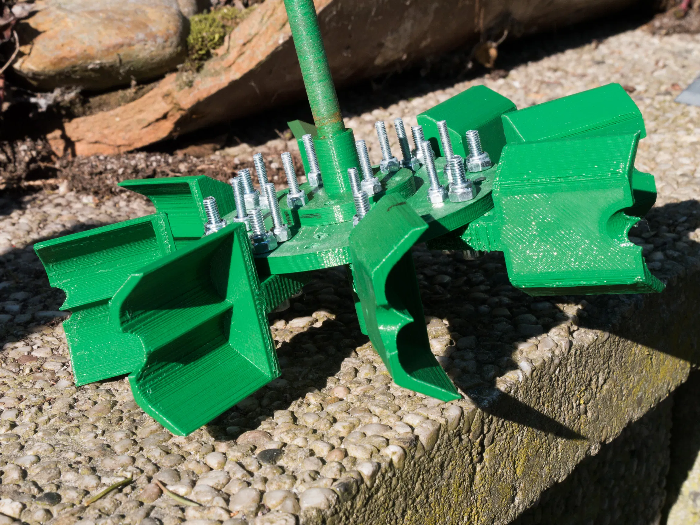
The turbine assembly:
I decided to initialy use an existing design for the Pelton buckets because my experience with drawing in Fusion 360 and designing things that can be made by a 3D printer was very limited when I started this project. The buckets are made by Laurentboom at thingyverse. eventualy I'm going to design my own buckets.
The current turbine has only eight buckets but it is possible to add another 8 buckets.
Turbine housing:
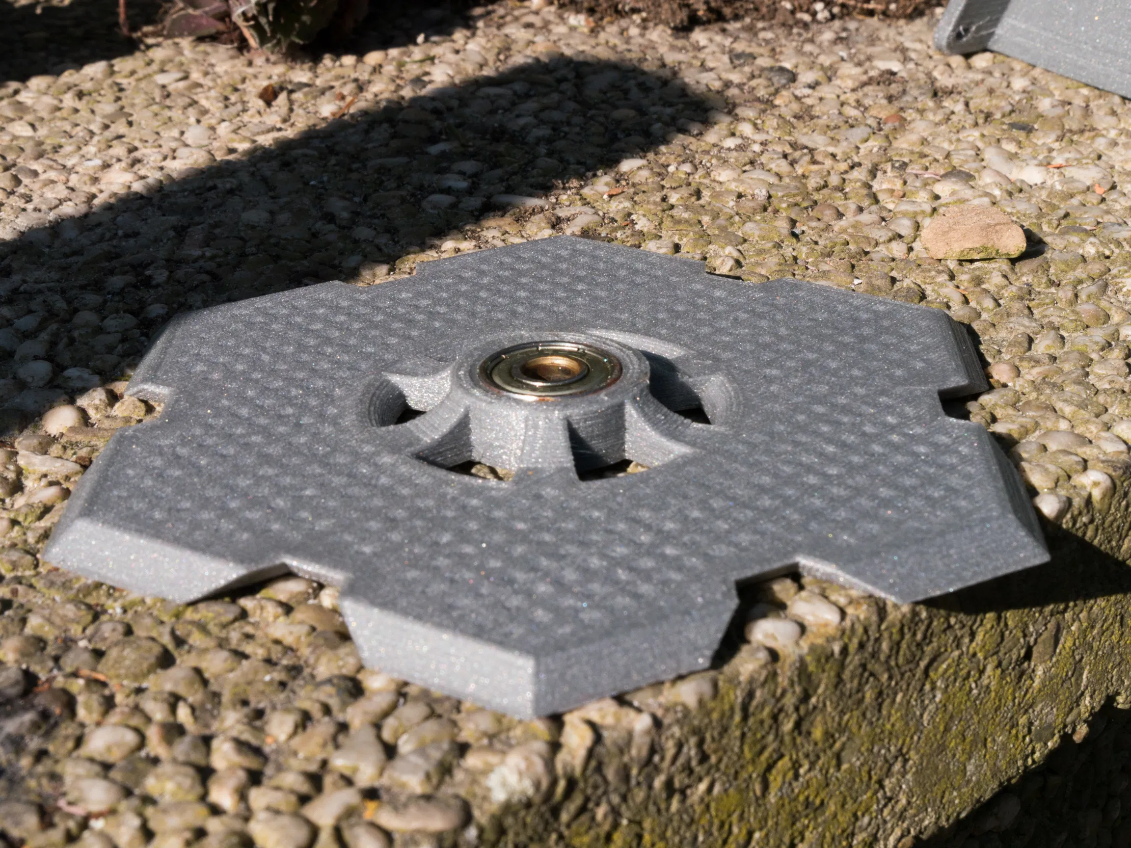
The turbine housing consist of eight parts, six “wall” sections and two center plates that hold the bearings.
On the center of every wall section is a hole that can be used to mount a nozzle. The holes are deliberately made oversized so it’s possible and easier to experiment a with different nozzle and mounting designs. The holes could also be used to let the water out if you want to use the turbine while standing on its side.
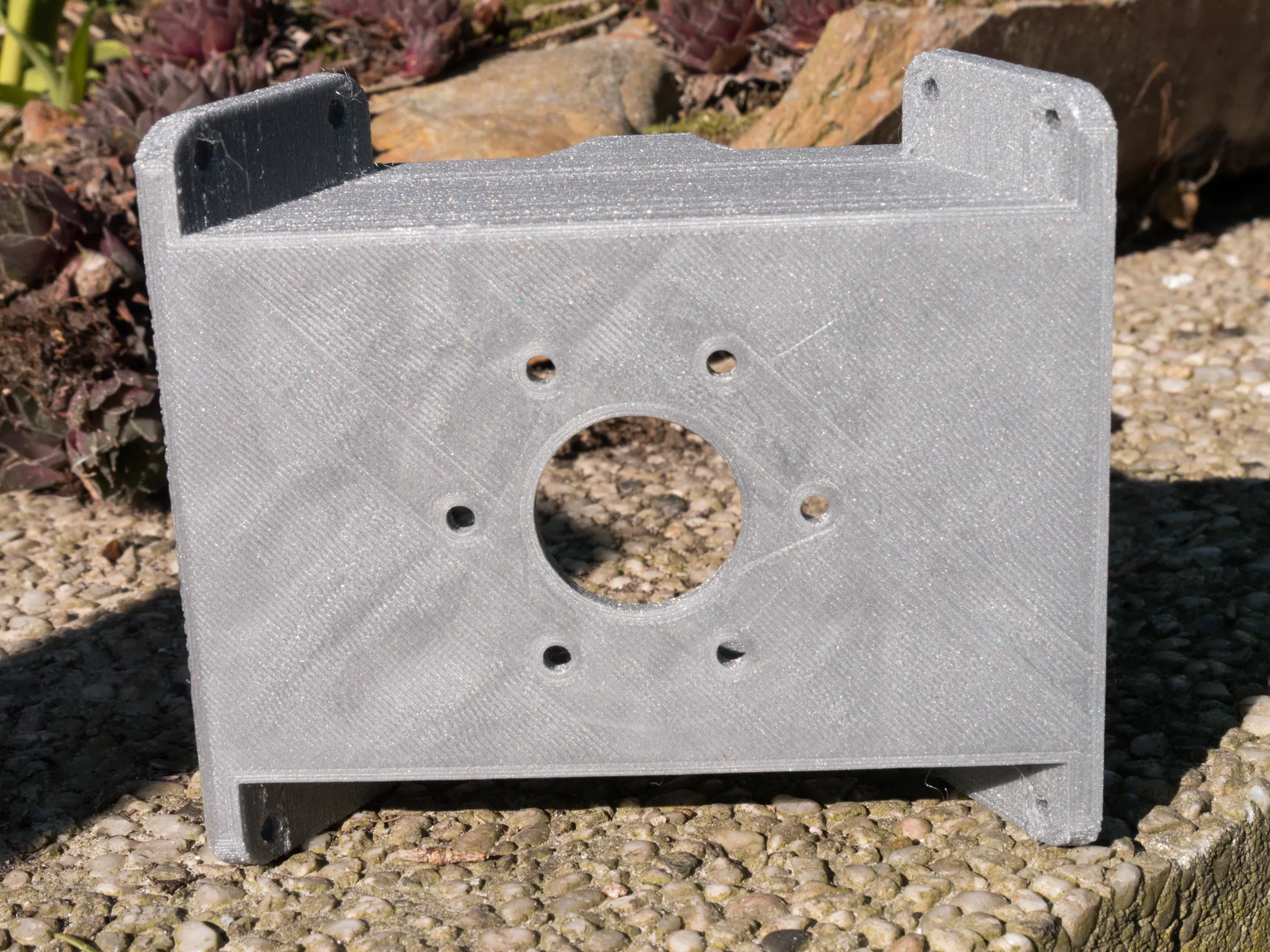
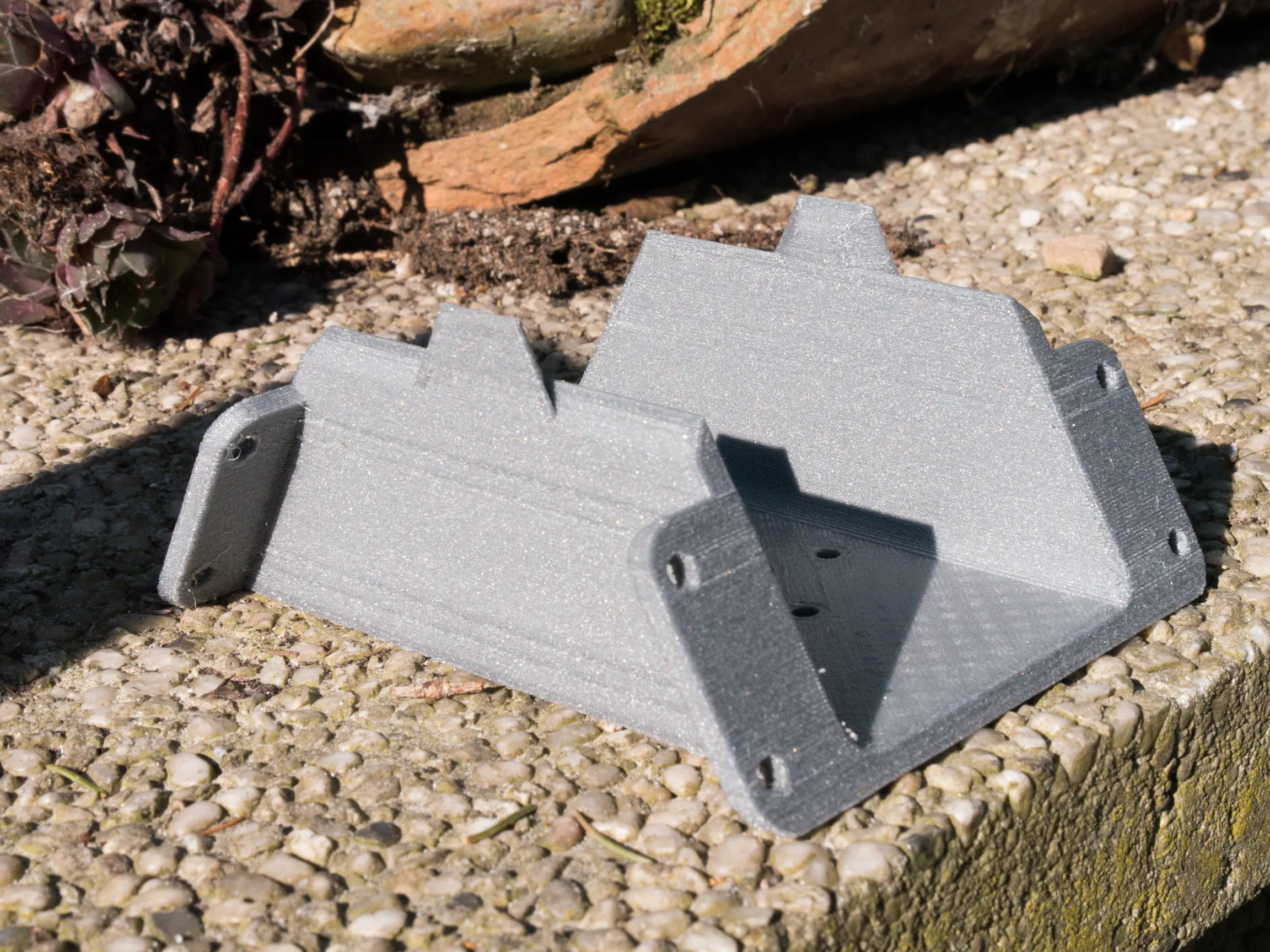
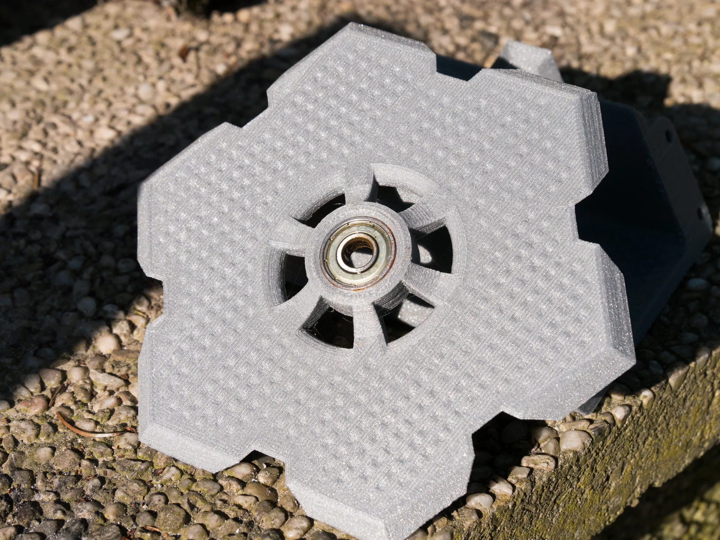
To simplify the build and design of the turbine house the same plate is being used for the top and bottom of the turbine housing. The holes around the bearing are there to let the water out of the turbinehousing. The center plates are held in place by being clamped in the center of the wall sections. This way of mounting the middle plates saves some nuts and bolts.
Nozzle assembly:
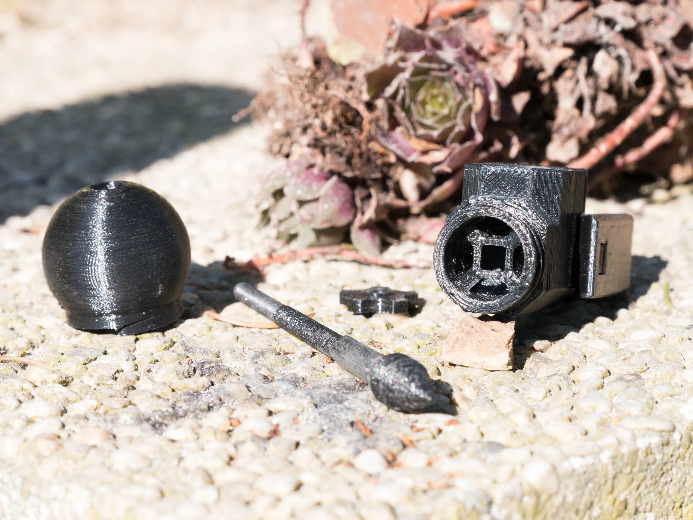
The nozzle assembly is what controls the flow of water onto the buckets. The nozzle assembly consists of five parts.
- Spear
- Round nozzle head
- Centerpiece
- Backpiece
- Controll nut
The spear is used to controll the flow of water, by rotating the control nut the spear can be moved foreward or backwards. For testing is used a round nozzle head that can be rotated a little bit to get the water flow on the right spot on the buckets. The nozzle is clamped between a plate and the wallsection.

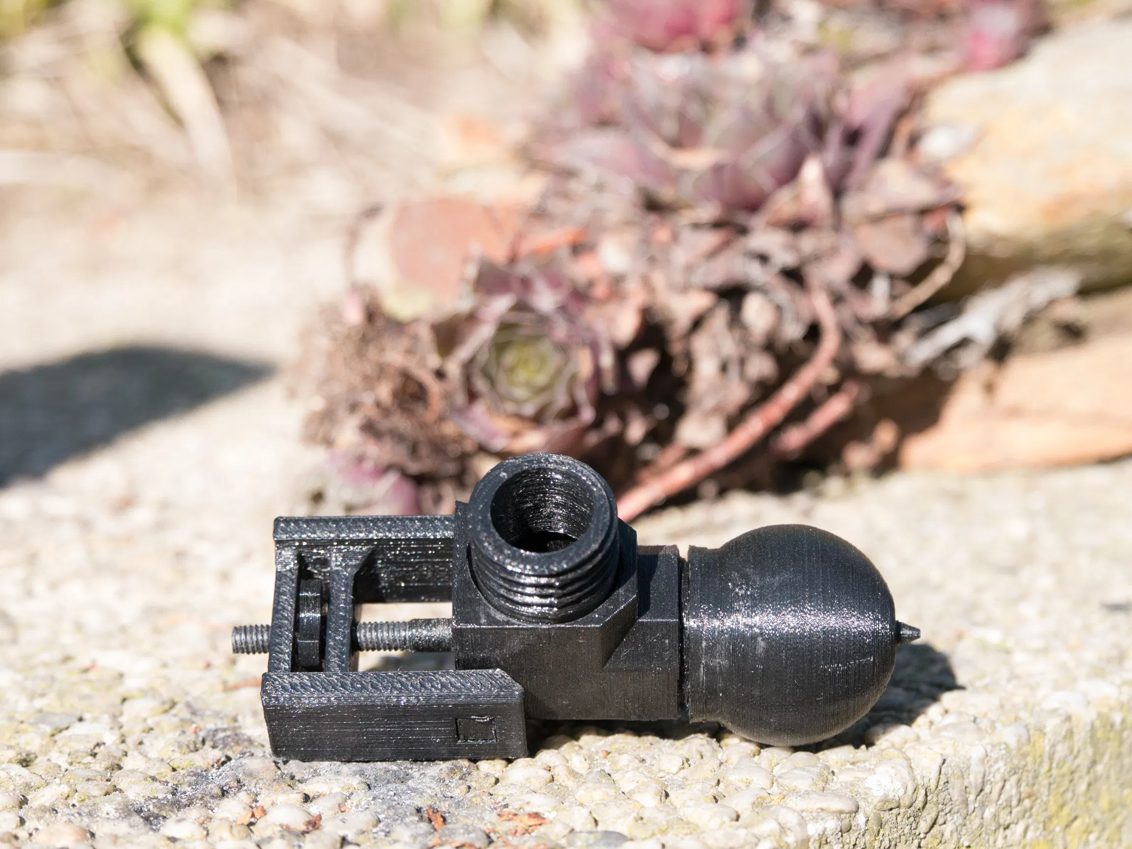
Now the big question is, Does it work?: Yes, buuuut there is alot that can be improved. The current nozzle needs to be redesigned. The walls of the nozzle head and center part need to be strengthened because the walls are currently are so thin that they easely crack when a small amount of tension is exerted when assembling the whole nozzle.
Also the 3D printed axle of the turbine assembly is not straight which causes the turbine not to rotate freely and because of this wasting alot of energy. This is more a problem of the limitation of the Anet A8 3D printer but it is something that needs to be taken in considereation when designing these parts.


originaly writen on August 29th, 2019